
This post is a hands-on look at the current state of development and a overview of how we plan to integrate the separate pieces of our design: our app, FMOD studio, and our embedded sensors.
We’ve integrated FMOD studio into our app and have begun testing it. This means the software that will play adaptive music is now on the same platform as our sensor data, which is being streamed from our embedded system to the app using BLE. There is no connectivity between FMOD and our sensor data (yet). For now, FMOD loads a default bank file to play music and the sensor data is displayed on the sensor page. With a custom bank file and a few tweaks to the FMOD API we should have custom adaptive music playing on our app.
All of our sensors are functional, including 9-axis IMU and hall effect sensors for speed. We are extremely close to having a functional prototype.
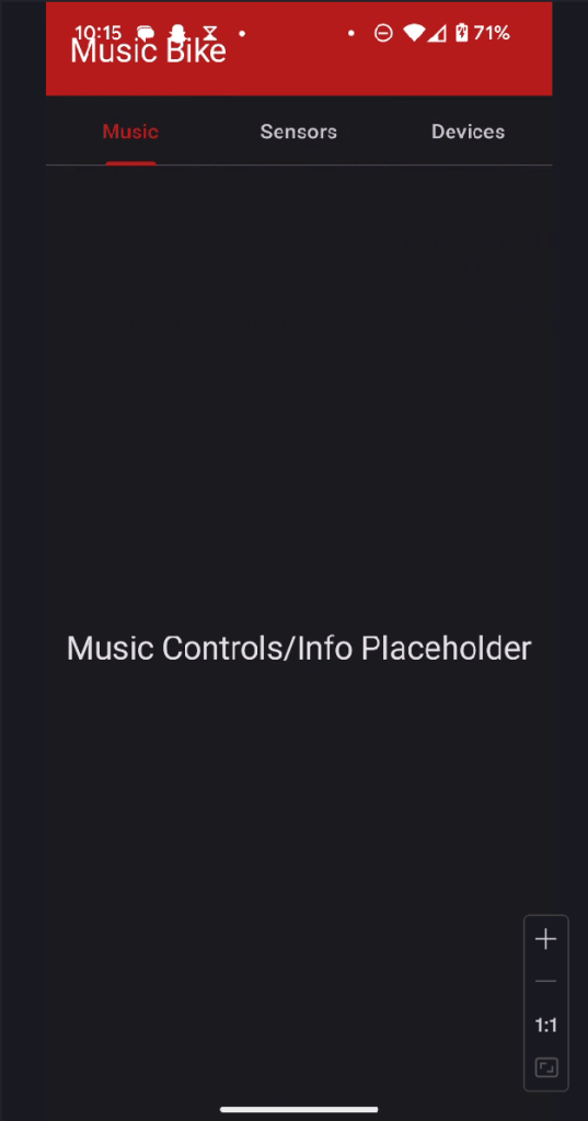

The main pages of our app. The functionality is currently very limited, but it shows how we intend to display data and controls for FMOD.
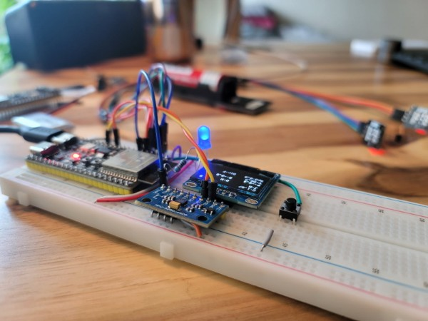
Our initial breadboard setup has evolved significantly since week three, serving as the foundation of our rapid prototyping approach. The flexibility of this configuration has allowed us to quickly test and implement new features without committing to permanent hardware decisions. Most recently, we added a second Hall effect sensor to detect direction changes based on wheel rotation and integrated a blue LED indicator that illuminates when Bluetooth connection is established. These seemingly small additions have dramatically improved our ability to gather meaningful data during testing sessions.
While the breadboard configuration has been ideal for bench testing and quick iterations, its inherent limitations—particularly the vulnerability to loose connections—make it unsuitable for on-bike testing. As we prepare to transition from controlled environment testing to real-world cycling conditions, we’re planning to migrate to a soldered prototype PCB board. This next-stage prototype will maintain the flexibility we need for continued iteration while providing the structural integrity required for mounting on a bicycle frame and withstanding the vibrations and movements of actual riding.
Next Steps
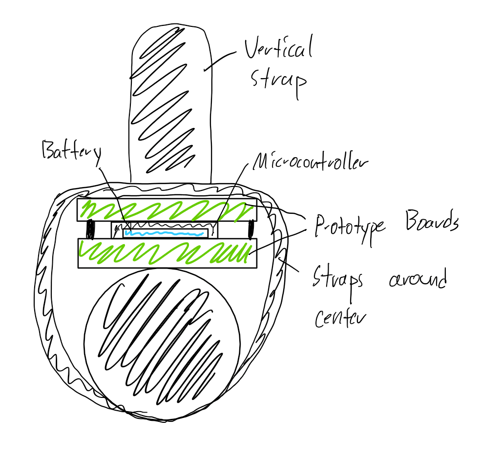
We are working on getting our embedded system mounted on a bicycle ASAP so we can start testing. We plan to use prototype PCBs to create a more secure mounting for our sensors and microcontroller. The microcontroller and sensors will be sandwiched between two prototype boards to form an enclosure, with the battery tucked underneath the microcontroller. This enclosure will be strapped to the bike.
We’re exploring different mounting options, but one option (described below) is to mount the sensor pack around the central strut near the water bottle holder. The sensor pack would be strapped around the strut and to the water bottle holder to prevent shifting.
Once the sensor pack is mounted to the bike, we plan to update the hall effect sensors to support directional wheel speed measurement. To do this, we’ll add an extra hall effect sensor placed next to the first on each wheel. The order that the hall effect sensors activate will be used to calculate direction.
That’s all for this week, next week we’ll have updates on the development of our app and FMOD integration.

Leave a comment