
This week was especially exciting because we finally mounted our sensor pack onto the bike. We faced difficulties getting I2C running with our new PCB but after a software update modifying the pin layout everything is working as it should.
Sensor Pack
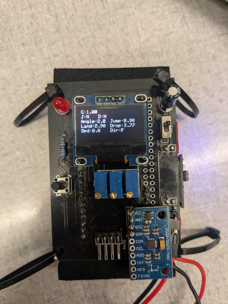
This is the top of our sensor pack. It contains the display, accelerometer zero button, power switch, IMU (bottom right) and potentiometers to adjust the jump/drop sensitivity. The pins on the bottom are used to connect to the hall effect sensors.
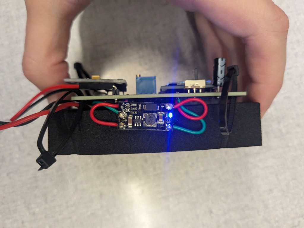
The side contains the power delivery board used to regulate the voltage of our attached lithium-ion battery.
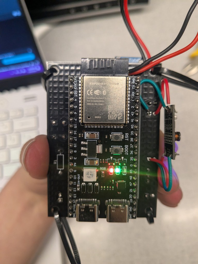
The back contains our microcontroller. This is typically covered by a piece of foam. The lithium-ion battery is placed in the void between the microcontroller and the PCB.
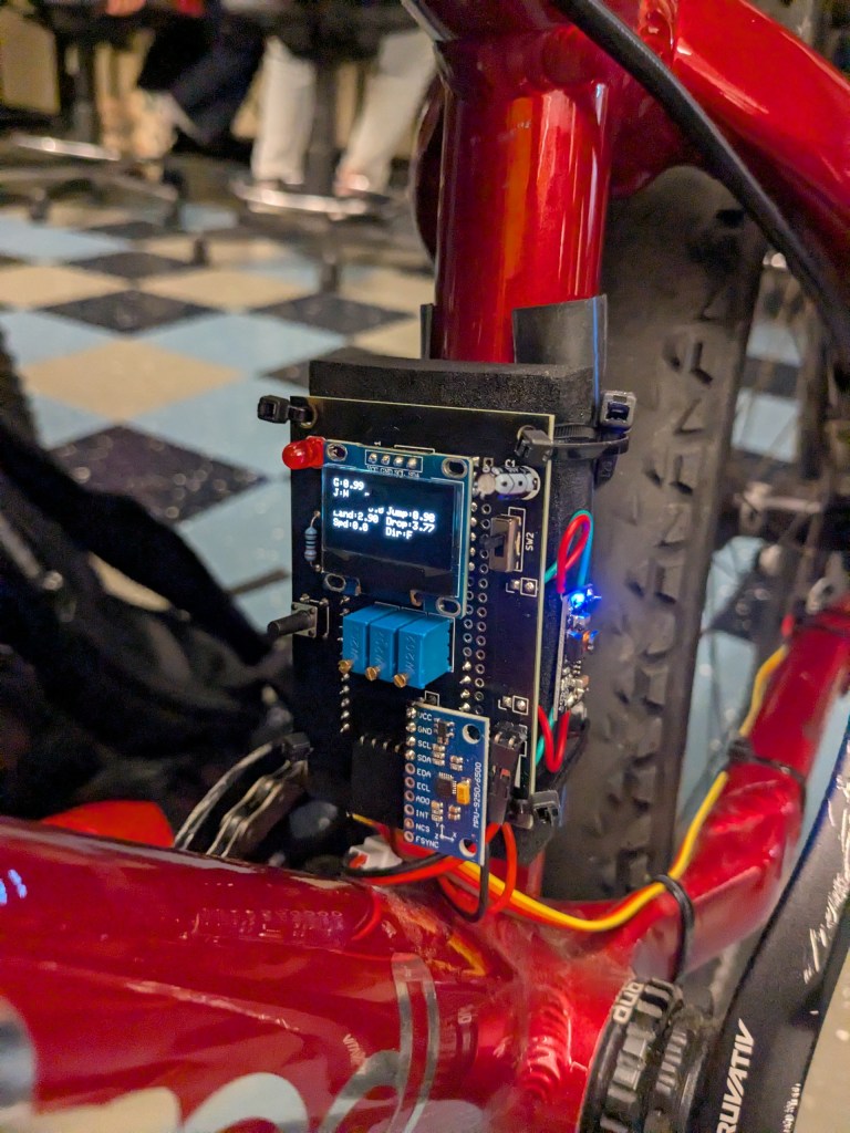
The sensor pack is mounted to the bike using a piece of rubber to reduce vibrations and zip ties (an inelegant but effective solution for now).
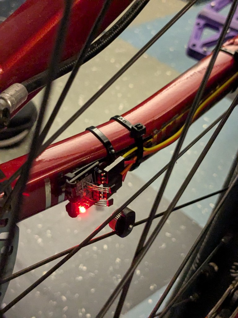
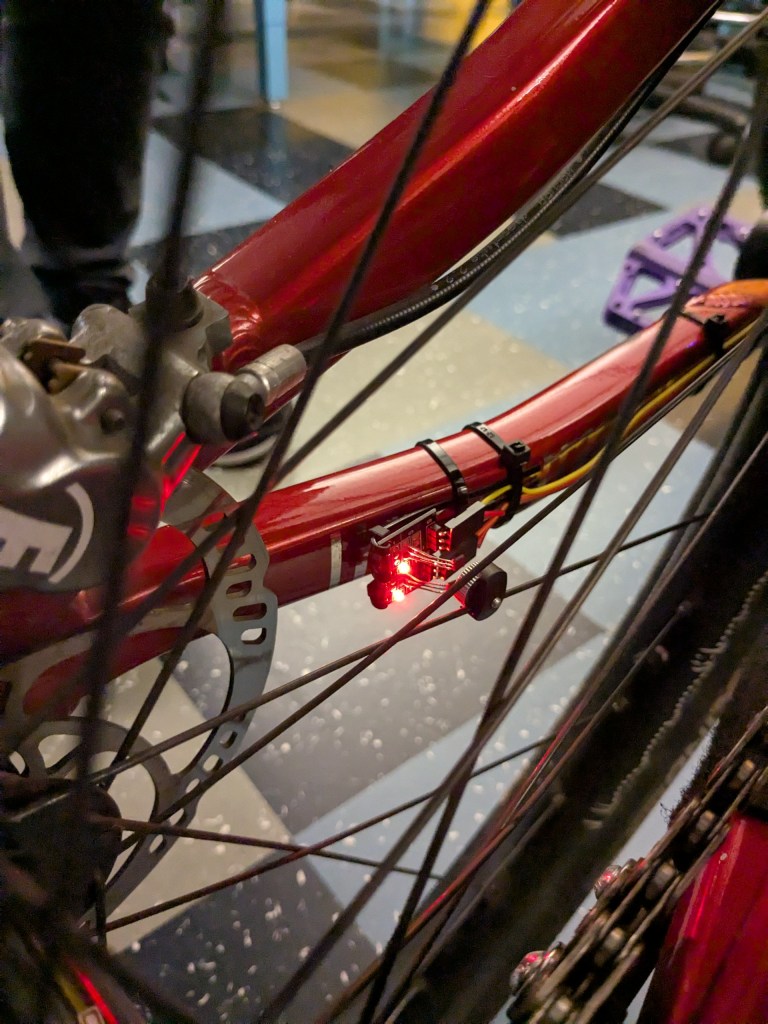
The hall effect sensors are mounted near the rear wheel hub, also with zip ties. The magnets attach to the spokes of the wheel. Two hall effect sensors are used to detect direction. In the photo above you can see how only one hall effect sensor is activated by the magnet, but in the photo below both hall effect sensors are active.
After mounting the sensor pack, we tested our system integration with the app playing an FMOD bank file. It worked well, although the music was jumpy. We plan to add more filtering to the accelerometer data processing, then begin training our machine learning model to detect tricks.
That’s it for this week! Stay tuned for week 9 as we continue system integration.

Leave a comment